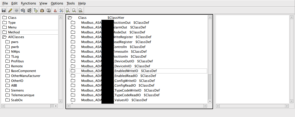
ProView provides a nice interface to build custom device classes, I/O classes and graphic classes, mainly to build processing graphics. In our current project we have many device configurations which are subject of repeated configurations. To avoid repetitive work we are using classes, of all kinds. Custom process graphics as components can avoid repetitive work with equal configurations and specific processing graphics. I have made a sample HMI — Human Machine Interface — to control some devices which will be used on the real plant.
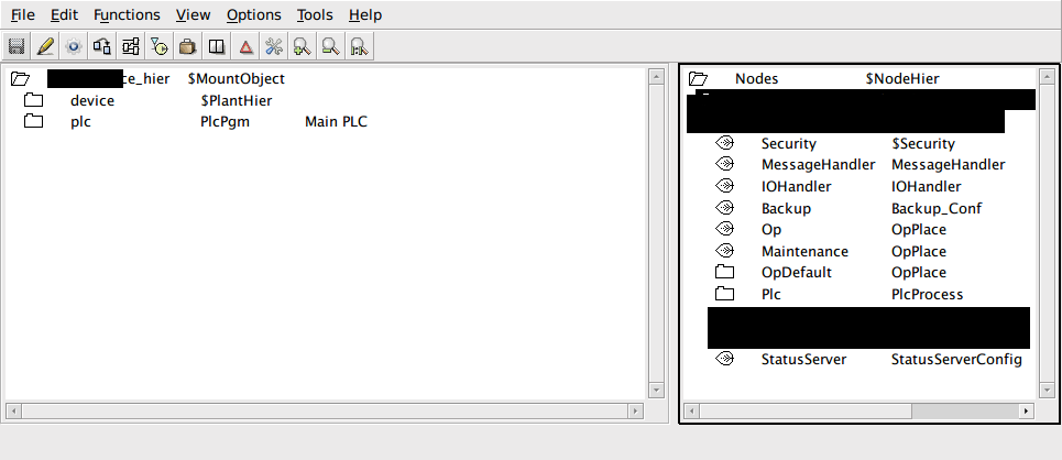
Is nice to have that kind of configurations, we have several classes for almost all layers and node types — both physical and logical nodes — allowing a higher level of abstraction and avoiding repeated configurations. We just need to setup the UnitId property on most objects — due to its Modbus base classes.
Also, as graphic component, we have configured some generic nodes — for logical nodes and I/O classes — where we have some nice interfaces as samples because the definitive HMI is not really defined yet. Still we are defining some algorithmic behavior of the controlling program, which is being developed using C and C++. Rather than defining an IoConnect reference attribute, you should create an object reference attribute and all sub-graph objects should be connected using $object as base reference, as it is being done using IoConnect object references.
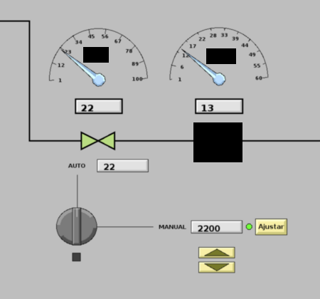
As this happens on the ProView side, the same happens on the C and C++ programming side. The code base has all device classes defined as they are ProView classes with their custom I/O methods and controlling logic. Also there are some signal transformations as it is being done by PLC programs but implemented in C, just to ensure that some signal objects have the proper representation as analog devices — like the percent needle.
So, finally is nice to work with this framework, it is very flexible, so the graphic object is being connected to the device node in the following picture.